Introduction
Use this web tool to draw a custom nozzle wiping path. It currently supports the Prusa Core One with Bambu Lab A1 silicone pads and pad mounting arms that place the pad at the front of the printer.
The recommended option is the Core One Nozzle Wiper V2 with Purge Bin wiping arm because it places the silicone pad fully within reach of the nozzle. Other arms, including version 1, may work but can leave part of the pad outside the nozzle's reach.
The sections below walk you step by step through creating your nozzle wiping sequence.
Select Your Printer
The tool will consider the printer's constraints and properties to adjust the instructions, G-code generation, and drawing area.
Silicone Pad Position Calibration
Use this section to record the silicone pad position so the tool can calculate the wiping coordinates accurately.
Step 1: Homing
After installing the wiper arm and silicone pad according to the documentation on Printables, home the printer via LCD Menu→Control→Auto Home on the LCD.
Step 2: Calibrate Silicone Pad Position
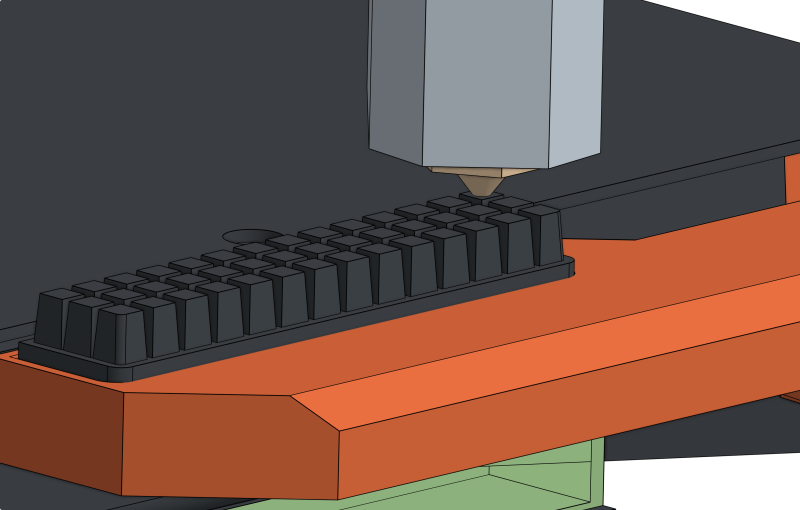
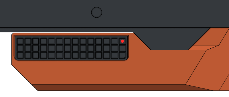
Via LCD Menu→Control→Move Axis→Move X / Move Y / Move Z, move the nozzle directly above the center of the top-right square of the silicone pad. This applies to both right- and left-sided versions of the nozzle wiper arm.
Set the Z-axis height so that the nozzle just barely touches the silicone pad.
The LCD only moves in 1mm increments, so a close approximation is fine. Eyeball the decimal points if your calibration point falls between millimeters.
Note the X, Y, and Z nozzle position coordinates shown on the LCD for the next step.
Step 3: Enter Nozzle Coordinates
Enter the nozzle position coordinates from the previous step into the form fields below.
Settings
Configure the values used to generate the wiping sequence G-code. Defaults are provided and usually do not need to be changed.
Plunge Depth
How far the nozzle lowers into the silicone pad during the wiping sequence.
Wiping Speed
Feed rate for the wiping sequence (mm/min).
Z-Lift
Lift the Z-axis after wiping before leaving the pad area. Enter 0 to disable.
Draw Wiping Path
G-Code
Testing
Testing Speed
Speed at which to test the wiping G-code at (based on feed rate from settings).
Download Test File
This test G-code recreates the Start G-code portion that handles wiping. It moves the nozzle to the parking position, performs the wiping path you drew, and then moves the nozzle to the center of the bed. That sequence matches how your printer will enter and exit wiping during a real print.
The test file runs at 5% of your configured feed rate (500 mm/min). The slower speed gives you time to press Reset on the LCD if you need to stop it and reduces the chance of damage if something collides.
It does not heat up the nozzle, so make sure there aren't any dangling filament bits stuck to the nozzle before running the test file.
Do not paste G-code from this test file into your Start G-code. Copy the G-code from the drawing section instead.
Installation
Copy the Wiping G-Code
In the Drawing section, click "Copy G-code" above the generated output.
Replace the Existing Cleaning in PrusaSlicer
Open PrusaSlicer and go to Printer Settings→Custom G-code→Start G-code.
Find the current nozzle cleaning command (G29 P9 X208 Y-2.5 W32 H4) and replace that line with the G-code you copied from this tool.
Keep the rest of your Start G-code unchanged. Only swap the original cleaning command for your new wiping path.
Save and Test
Save the printer profile. Run a small test print and confirm the new wiping path runs in place of the old cleaning routine.